Skip to product information
1 of 1

POWER PROBE · PPECB

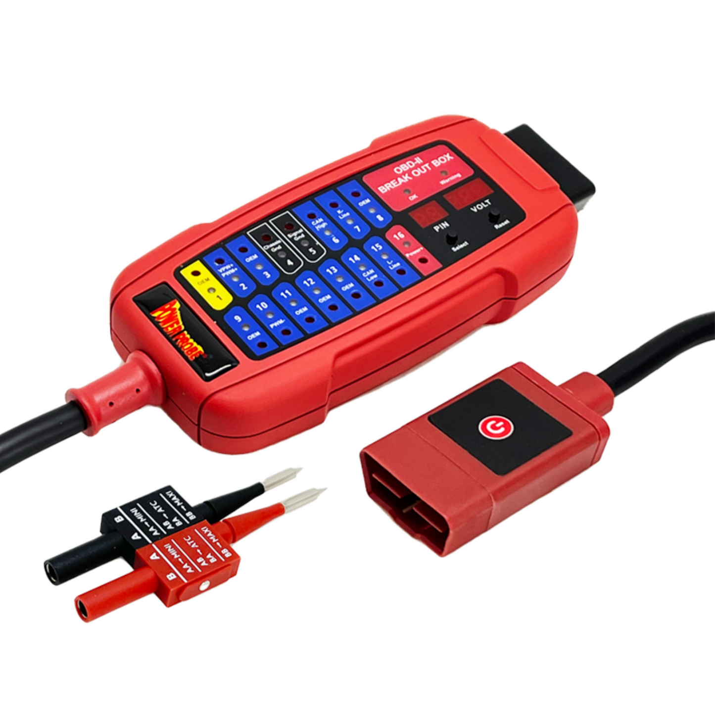
OBD-II Breakout Box

OBD-II Breakout Box

Check the OBD-II port before you connect your scan tool.

Regular price $339.95
Regular price Sale price $339.95
Sale Sold out
Shipping calculated at checkout.
  • Protect diagnostic equipment by checking the DLC first for abnormal voltage, shorts, and reversed polarity before plugging in a scanner.
  • Monitor live communication activity with color-coded LED indicators for protocol signals and constant voltage across the OBD-II pins.
  • Access and test all 16 OBD-II pins individually while monitoring voltage and receiving audible warnings for low or high system voltage.
Product description

The Power Probe® OBD-II Breakout Box is a CANBUS circuit tester that plugs directly into the Vehicle’s Data Link Connector (DLC). This will test for any abnormalities such as shorting and reverse polarity at the DLC pins before a Diagnostic Scan Tool is plugged in preventing damage to diagnostic equipment. The Breakout Box provides live display of present communication signals without having to use a Digital Multimeter.

Technical specifications

• Operating range: 7.0 - 30.0VDC Input.
• Maximum load: Up to 3.0 Amps Output.
• Overload protection: Yes, PTC Fuse (Self-healing)
• Volt displays: 3 Digits LEDs (Resolution: 0.1V)
• Banana sockets: 16 outputs x 1.0mm diameter with LED lamp indications.
• Protocols detected: PWM (J1850), VPW (J1850), ISO 9141-2, DIS/ISO
14230-4, CAN bus (J-2284)
• Operating temperature:32°F - 122°F(0°C - 50°C)
• Permitted humidity:Less than 70%.
• OBD cable length:30 inches (0.8 meter)
• Reverse polarity protection:Yes, LED on pin 4 & 5 turns red.
• Warning beeps:
• Slow beeps:Below 11.8V/23.6V (Low Voltage)
• Fast beeps:Above 15.5V/31.0V (High Voltage)

What’s included

• OBD-II
• 2 pin adapter (PPTK0048)
• Instructions manual

User Manual
Shipping & returns
View full details

Verify the port. Watch the signals. Access every pin.

OBD-II port protection

Check the diagnostic link connector for shorts, abnormal voltage, and reversed polarity before connecting a scan tool, helping prevent avoidable equipment damage.

Live protocol monitoring

See communication activity as it happens with color-coded LEDs for PWM, VPW, ISO 9141-2, ISO 14230-4, and CAN bus signals. Blue or yellow indicates pulse communication on supported pins, while red indicates constant voltage.

16-pin access & voltage monitoring

Connect directly to all 16 DLC pins for testing and diagnosis, with a built-in voltmeter, pin selection, low/high voltage alarms, and support for 12V and 24V systems.